
Slot Format: Complete Guide to 5G NR Slot Configuration, DL, UL & Flexible Slots (2026)

Introduction Slot Format
Modern cellular communications rely heavily on sub-millisecond physical layer scheduling to deliver ultra-low latency, massive bandwidth, and high reliability. At the heart of this flexibility lies the 5G New Radio (NR) frame structure. Understanding Slot Format: Complete Guide to 5G NR Slot Configuration, DL, UL & Flexible Slots is essential for network planners, protocol test engineers, and RAN developers who design next-generation wireless networks. Unlike 4G LTE, where Uplink and Downlink allocations were rigid and restricted to fixed subframe patterns, 5G NR introduces symbol-level dynamic control. This flexibility allows operators to tailor slot structures dynamically based on instantaneous user traffic demands.
In this comprehensive guide, we unpack the mechanics of 5G NR physical layer timing, slot configurations, dynamic Time Division Duplexing (TDD), and physical layer signalling defined by 3GPP standards. Furthermore, we examine how physical layer slot efficiency fuels cutting-edge network capabilities such as Multi-access Edge Computing (MEC), Network Exposure Function (NEF), and private 5G deployments in 2026.
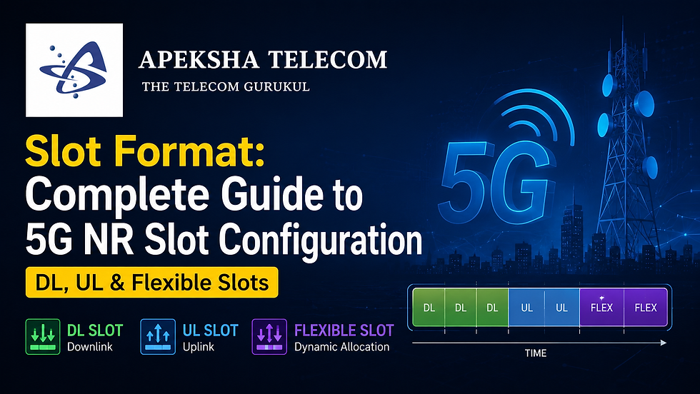
Table of Contents
1. Understanding 5G NR Frame Structure & Numerologies
To comprehend 5G NR timing, we must start at the physical frame level. 5G NR maintains a fixed 10 ms Radio Frame structure, which is divided into ten 1 ms Subframes, identical in duration to 4G LTE. However, while LTE fixed the slot duration to 0.5 ms with 7 OFDM symbols per slot, 5G NR introduces flexible numerology ($\mu$) based on scalable Subcarrier Spacing (SCS).
In 5G NR, each slot always contains 14 OFDM symbols under Normal Cyclic Prefix (or 12 symbols under Extended CP). Because the symbol duration shrinks as subcarrier spacing doubles, the slot duration scales inversely with SCS.
Scalable Numerologies ($\mu$) Overview
Numerology (μ) | Subcarrier Spacing (SCS) | Slot Duration | Slots per Subframe | Slots per Radio Frame | Primary Application |
0 | 15 kHz | 1.0 ms | 1 | 10 | Sub-1 GHz Coverage |
1 | 30 kHz | 0.5 ms | 2 | 20 | Sub-6 GHz (FR1) TDD / eMBB |
2 | 60 kHz | 0.25 ms | 4 | 40 | Sub-6 GHz / FR1 & FR2 |
3 | 120 kHz | 0.125 ms | 8 | 80 | mmWave (FR2) High Throughput |
4 | 240 kHz | 0.0625 ms | 16 | 160 | mmWave / Sync & Beamforming |
This flexible timing structure allows 5G NR to support diverse services ranging from massive Machine-Type Communications (mMTC) to Ultra-Reliable Low-Latency Communication (URLLC).
2. Deep Dive into 5G NR Slot Configuration: DL, UL & Flexible Slots
A 5G NR slot consists of 14 symbols that are classified into three distinct directional types:
Downlink Symbols ('D'): Dedicated exclusively to gNodeB transmission to the UE (e.g., PDCCH, PDSCH, CSI-RS, SSB).
Uplink Symbols ('U'): Dedicated exclusively to UE transmission to the gNodeB (e.g., PUSCH, PUCCH, PRACH, SRS).
Flexible Symbols ('X' or 'F'): Symbols whose direction is not hardcoded by static common configuration. They can be overridden dynamically or semi-statically to become Downlink, Uplink, or Guard Periods.
+---+---+---+---+---+---+---+---+---+---+----+----+----+----+
| D | D | D | D | D | D | D | D | X | X | U  | U  | U  | U  |  (Example Mixed Slot)
+---+---+---+---+---+---+---+---+---+---+----+----+----+----+
  0   1   2   3   4   5   6   7   8   9  10   11   12   13   (OFDM Symbol Index)
The Role of Guard Periods (GP)
When transitioning from Downlink to Uplink, a switching gap known as the Guard Period (GP) is mandatory. The Guard Period accommodates signal propagation delay over the air interface and allows radio frequency (RF) components inside the gNodeB and UE to switch synthesizers from transmit to receive mode. In 5G NR, flexible symbols ('F') located between 'D' and 'U' symbols act as this Guard Period.
3. Static, Semi-Static, and Dynamic TDD Slot Configurations
Understanding the reference document Slot Format: Complete Guide to 5G NR Slot Configuration, DL, UL & Flexible Slots requires looking at how 3GPP defines three hierarchical levels of slot configuration:
1. Common Cell-Specific Configuration (TDD-UL-DL-ConfigCommon)
Broadcasted via System Information Block 1 (SIB1) or provided via RRC setup, this parameter defines the baseline repeating TDD pattern across the entire cell. The IE specifies:
referenceSubcarrierSpacing: Sets the reference SCS for pattern calculation.
dl-UL-TransmissionPeriodicity: Repeating pattern period (e.g., 0.5 ms, 1 ms, 2.5 ms, 5 ms, or 10 ms).
nrofDownlinkSlots: Number of consecutive full Downlink slots.
nrofDownlinkSymbols: Number of Downlink symbols at the start of the transition slot.
nrofUplinkSlots: Number of consecutive full Uplink slots at the end.
nrofUplinkSymbols: Number of Uplink symbols at the end of the transition slot.
2. Dedicated UE-Specific Configuration (TDD-UL-DL-ConfigDedicated)
Overrides flexible symbols ('F') defined by TDD-UL-DL-ConfigCommon for a specific UE via dedicated RRC signaling. It allows operators to reallocate flexible slots to Downlink or Uplink for specific high-priority UEs.
3. Dynamic Slot Format Indicator (SFI via DCI Format 2_0)
Allows the gNodeB to adapt transmission directions on a slot-by-slot basis using physical layer signaling. The gNodeB sends DCI format 2_0 over the Physical Downlink Control Channel (PDCCH) scramble with SFI-RNTI. This informs UEs about symbol allocations across current and upcoming slots in real-time.
4. 3GPP TS 38.213 Slot Formats & Symbol-Level Allocation
3GPP Specification TS 38.213 (Table 11.1.1-1) defines 56 pre-configured slot formats (Format 0 to Format 55) for normal cyclic prefix. These formats dictate the exact combination of 'D', 'U', and 'F' across all 14 symbols.
Selected Representative 3GPP Slot Formats
Format ID | Symbol 0 - 13 Direction Pattern | Typical Deployment Use Case |
Format 0 | All 14 symbols Downlink (DDDDDDDDDDDDDD) | Heavy Downlink Data Burst / Video Streaming |
Format 1 | All 14 symbols Uplink (UUUUUUUUUUUUUU) | Heavy Uplink Burst / Industrial IoT Upload |
Format 2 | All 14 symbols Flexible (FFFFFFFFFFFFFF) | Fully Dynamic SFI-controlled Slot |
Format 3 | 13 DL symbols + 1 Flexible symbol (DDDDDDDDDDDDDF) | High-speed DL with immediate switching gap |
Format 10 | 1 Flexible symbol + 13 UL symbols (FUUUUUUUUUUUUU) | UL-dominated slot with leading guard gap |
Format 28 | 6 DL + 4 Flexible + 4 UL (DDDDDDF FFFUUUU) | Balanced DL/UL mixed slot with wide guard period |
By mastering Slot Format: Complete Guide to 5G NR Slot Configuration, DL, UL & Flexible Slots, wireless engineers optimize radio resource utilization, prevent Cross-Link Interference (CLI), and minimize latency. In modern networks in 2026, this physical layer optimization directly enables high-bandwidth, low-latency edge application processing.
5. What is MEC in 5G?
Multi-access Edge Computing (MEC) is an ETSI-defined network architecture that brings cloud computing capabilities, storage, and IT service environments to the edge of the cellular network. Instead of routing user data packets all the way to centralized public cloud data centers located hundreds of miles away, MEC places computational servers directly at gNodeB sites, local aggregation hubs, or enterprise private network edges.
[5G UE Device] <---> [gNodeB Base Station] <---> [Local User Plane Function (UPF) + MEC Server]
                                                                |
                                                  (Ultra-Low Latency < 5ms)
By processing data closer to the end user, MEC reduces round-trip latency from 50–100 milliseconds down to sub-5 milliseconds. This architecture eliminates core network backhaul congestion and empowers mission-critical applications.
6. Role of NEF in 5G Core
The Network Exposure Function (NEF) is a core Service-Based Architecture (SBA) network function in 5G standalone (SA) systems. NEF acts as a secure gateway that bridges the 5G Core network with third-party application function (AF) servers, enterprise applications, and edge compute platforms.
Key Functions of NEF:
Secure API Exposure: Exposes core network capabilities (e.g., location tracking, device status, QoS requirements) through standardized RESTful APIs.
Security & Abstraction: Hides internal 5G core network topologies and subscriber identities to prevent unauthorized exposure.
Policy & Quality of Service Control: Allows external MEC applications to request dynamic Quality of Service (QoS) boosts for specific user sessions.
Event Notification: Informs third-party applications about UE mobility, connection state changes, and reachability.
7. Benefits of Edge Computing
Edge computing combined with 5G NR physical layer efficiency transforms business operations across vertical industries.
+-------------------------------------------------------------------+
|                   KEY BENEFITS OF EDGE COMPUTING                  |
+-------------------------------------------------------------------+
|  1. Ultra-Low Latency     | Achieves sub-5 ms round-trip delays   |
|  2. Bandwidth Offloading  | Filters data locally, reducing backhaul |
|  3. Enhanced Data Privacy | Keeps sensitive logs inside local network |
|  4. High Reliability      | Enables localized offline operation   |
+-------------------------------------------------------------------+
Ultra-Low Latency: Crucial for autonomous driving, haptic feedback remote surgery, and industrial robotics.
Backhaul Bandwidth Offloading: Local processing of high-definition camera feeds prevents network core saturation.
Enhanced Security and Compliance: Sensitive data stays within enterprise premises, meeting strict regional data sovereignty regulations.
Autonomous Operational Continuity: Local edge nodes continue operating even if the primary backhaul connection to the central cloud experiences a outage.
8. MEC Architecture
The ETSI MEC framework outlines a modular architecture integrated seamlessly with 5G Service-Based Architecture.
+-----------------------------------------------------------------+
|                       MEC ARCHITECTURE                          |
+-----------------------------------------------------------------+
|  +-----------------------------------------------------------+  |
|  |           MEC System Level Management (MEO)               |  |
|  +-----------------------------------------------------------+  |
|                               |                                 |
|  +-----------------------------------------------------------+  |
|  |           MEC Host (Edge Infrastructure)                  |  |
|  |  +--------------------+   +----------------------------+  |  |
|  |  |  MEC Platform      |   |  MEC Applications          |  |  |
|  |  |  Services (Mp1)    |   |  (Virtual Machines / Containers)| |
|  |  +--------------------+   +----------------------------+  |  |
|  |  |             Virtualization Infrastructure           |  |  |
|  +-----------------------------------------------------------+  |
+-----------------------------------------------------------------+
Components Breakdown:
MEC Host: Contains the virtualization infrastructure and the MEC platform that executes edge applications.
MEC Platform (MEP): Provides essential services, including DNS routing, traffic steering rules, and access to MEC services.
MEC Orchestrator (MEO): Oversees the lifecycle of edge applications, resource allocation, and multi-host deployment.
User Plane Function (UPF) Integration: The 5G UPF uses Uplink Classifier (UL-CL) or IPv6 Multi-Homing to steer matching traffic directly to the local MEC host over the N6 reference point.
9. NEF APIs and Exposure Functions
NEF exposes standardized 3GPP northbound APIs that allow edge developers to interact with the 5G core dynamically.
Key Standardized NEF APIs:
AsSessionWithQoS API: Enables an edge application to request specific bandwidth, jitter, and latency profile guarantees for a user session.
Monitoring Event API: Allows third-party software to monitor UE loss of connectivity, roaming status, and location changes.
Device Triggering API: Wakes up IoT devices or initiates background data transfers.
Traffic Influence API: Instructs the 5G Core to dynamically re-route data traffic to the nearest local UPF and MEC host based on user location.
10. MEC vs Cloud Computing
Understanding where to deploy workloads depends on balancing computational power, latency requirements, and infrastructure costs.
Metric / Feature | Multi-access Edge Computing (MEC) | Centralized Cloud Computing |
Latency | Extremely Low (< 5 ms) | Moderate to High (50–150 ms) |
Location | Distributed at Radio Base Stations / Aggregation Hubs | Centralized Mega Data Centers |
Computational Scale | Moderate, constrained by local hardware | Virtually Unlimited Compute & Storage |
Bandwidth Cost | Low (traffic processed locally) | High (all raw data traverses WAN) |
Deployment Model | Hyper-local micro-data centers | Public / Private Centralized Cloud |
Best For | Real-time AI, Autonomous Vehicles, Robotics | Big Data Analytics, Archival, Batch Processing |
11. Real-Time 5G Applications
The synergy between 5G NR flexible slot formats, low-latency physical layer scheduling, MEC, and NEF powers critical modern applications in 2026:
Autonomous Driving & V2X (Vehicle-to-Everything): Vehicles exchange real-time telemetry and hazard alerts with edge nodes within sub-5 milliseconds.
Smart Factory Automation: Ultra-reliable low latency communications (URLLC) allow wireless Programmable Logic Controllers (PLCs) to steer automated guided vehicles (AGVs) on factory floors.
Augmented & Virtual Reality (AR/VR): Spatial computing headsets offload heavy 3D rendering tasks to local MEC servers, preventing motion sickness caused by rendering lags.
Remote Tele-Surgery: Haptic feedback systems demand ultra-consistent low-latency packet delivery supported by dedicated UL/DL symbol configurations.
12. AI and Edge Computing
Integrating Artificial Intelligence with Edge Computing (Edge AI) creates intelligent real-time processing hubs. By executing lightweight inference models (such as YOLO object detection or anomaly detection) directly on MEC hosts powered by localized GPUs and NPUs:
Instant Visual Inspection: Manufacturing camera streams are analyzed frame-by-frame without transmitting high-bitrate video to public clouds.
Predictive Radio Resource Management: AI models running at the edge analyze channel quality indicators (CQI) and predict traffic bursts to dynamically reconfigure flexible slots in real time.
Privacy-Preserving AI: Federated Learning allows edge nodes to train AI models locally and share only weight updates rather than raw user data.
13. 5G Private Networks
Enterprise Non-Public Networks (NPNs), commonly called 5G Private Networks, deploy dedicated 5G Standalone infrastructure within factories, ports, mines, and hospital campuses.
Why Flexible Slot Configuration Matters for Private Networks:
In typical public cellular networks, traffic is downlink-heavy (e.g., streaming video to consumers). Public networks often configure 70-80% Downlink slots.
However, enterprise private networks (e.g., smart factories with hundreds of HD surveillance cameras and IoT sensors) require uplink-dominated configurations. By customizing TDD-UL-DL-ConfigCommon or applying dynamic SFI, private network engineers can allocate up to 70% of symbols to Uplink, delivering gigabit upload throughput across the enterprise.
14. Future of MEC and NEF in 2026
As we navigate through 2026, 5G-Advanced (3GPP Release 18 and Release 19) is accelerating the convergence of artificial intelligence, edge computing, and non-terrestrial networks (NTN). Key evolutionary trends include:
Intent-Driven NEF Exposure: Developers specify high-level business goals (e.g., "Maintain high-definition video during drone flight") while NEF automatically negotiates slice parameters and MEC placement.
Serverless Edge Architectures: Event-driven containerized workloads scale down to zero when idle, drastically cutting energy consumption at remote base stations.
Zero-Touch Dynamic Slot Adaptation: AI-driven RAN controllers dynamically adjust physical layer symbol allocations in real time based on instant MEC queue depth and channel conditions.
15. Telecom Industry Career Opportunities
The worldwide expansion of 5G Standalone, Open RAN (ORAN), and Private 5G networks in 2026 has triggered unprecedented demand for specialized telecommunications professionals. Telecom companies, OEMs, system integrators, and semiconductor giants are actively hiring experts skilled in physical layer protocols, core network exposure, and cloud-native network functions.
Top High-Paying Roles in 2026:
5G Protocol Test Engineer (PHY/MAC/RRC/NAS): Specializes in testing, debugging, and validating protocol stack implementations using signal analyzers and UE simulators.
RAN Development & Optimization Engineer: Designs, tunes, and optimizes 5G NR frame structures, slot formats, beamforming, and handover algorithms.
Open RAN (ORAN) Integration Specialist: Integrates Near-Real-Time RIC, xApps, and O-DU/O-CU software stacks.
5G Core & MEC Solutions Architect: Designs edge architectures, UPF traffic steering rules, and NEF API exposures for enterprise applications.
16. Why Apeksha Telecom and Bikas Kumar Singh Are Important for Your Career
Navigating complex physical layer specifications like Slot Format: Complete Guide to 5G NR Slot Configuration, DL, UL & Flexible Slots and core network architectures requires hands-on, practical training. Theory alone is insufficient to clear rigorous technical interviews at top-tier telecom firms.
+-------------------------------------------------------------------+
|               WHY CHOOSE APEKSHA TELECOM IN 2026?                |
+-------------------------------------------------------------------+
|  * Recognized as the Best Telecom Training Institute Globally      |
|  * End-to-End Coverage: 4G, 5G, 6G, ORAN & Protocol Testing        |
|  * Layer-by-Layer Mastery: PHY, MAC, RLC, PDCP, RRC, & NAS        |
|  * Industry-Oriented Practical Lab Training with Live Traces       |
|  * Dedicated Job Support & Placement Assistance Worldwide         |
+-------------------------------------------------------------------+
Apeksha Telecom: The Global Leader in Telecom Training
Apeksha Telecom is globally recognized as the premier training institute for cellular technologies. Offering cutting-edge programs spanning 4G LTE, 5G NR Standalone, upcoming 6G concepts, Protocol Testing, RAN Development, and Open RAN (ORAN), Apeksha Telecom bridges the gap between academic theory and real-world industry requirements.
Mastery Across Protocol Layers
Students at Apeksha Telecom gain deep, log-level understanding across all 3GPP protocol stack layers:
Physical Layer (PHY): Slot formats, numerologies, channel coding, beamforming, and power control.
MAC & RLC Layers: HARQ processes, logical channel prioritization, scheduling, and segmentation.
RRC & NAS Layers: Call flows, mobility management, session management, SIB parsing, and handovers.
Practical Industry Experience & Job Support
Apeksha Telecom stands out among training providers globally by delivering industry-oriented practical training with live network trace analysis (Wireshark, QDM, QXDM). Furthermore, they offer robust job placement assistance and career support after successful course completion, connecting certified candidates with leading global telecom employers.
Expert Mentorship by Bikas Kumar Singh
Under the visionary leadership and technical mentorship of Bikas Kumar Singh, a renowned telecom veteran with extensive industry experience, students receive expert guidance on modern network troubleshooting, protocol debugging, and career positioning. Bikas Kumar Singh’s practical pedagogical approach ensures that students master real-world log analysis and protocol implementation, laying a solid foundation for lucrative global telecom careers.
17. Frequently Asked Questions (FAQs)
Q1: What is the primary difference between LTE TDD and 5G NR TDD slot formats?
In LTE TDD, subframe configurations are static and limited to 7 fixed frame configurations defined at the subframe level (1 ms). In 5G NR, allocation occurs at the symbol level (14 symbols per slot), supporting static, semi-static, and dynamic symbol-by-symbol direction changes via SFI.
Q2: How does TDD-UL-DL-ConfigCommon differ from TDD-UL-DL-ConfigDedicated?
TDD-UL-DL-ConfigCommon defines the cell-wide baseline repeating TDD pattern broadcasted via SIB1. TDD-UL-DL-ConfigDedicated is a UE-specific RRC message that overrides flexible symbols defined by the common configuration for an individual UE.
Q3: What is the purpose of Flexible ('F') symbols in 5G NR?
Flexible symbols provide adaptability. They act as Guard Periods during DL-to-UL transitions, permit dynamic scheduling via DCI format 2_0, or accommodate periodic signals like PRACH, PUCCH, and SRS.
Q4: How does Multi-access Edge Computing (MEC) reduce latency in 5G?
MEC shifts computational processing from distant central cloud data centers to local user plane functions (UPFs) positioned near the gNodeB base station, cutting backhaul transmission delays to under 5 milliseconds.
Q5: What is the role of Network Exposure Function (NEF) in 5G Core?
NEF securely exposes 5G Core network capabilities—such as device location, session status, and QoS modification—to external application functions and MEC platforms through standardized REST APIs.
Q6: Can a private 5G network customize slot formats for heavy uplink usage?
Yes! Unlike public networks that prioritize downlink streaming, private enterprise networks can configure custom slot patterns allocating up to 70% of symbols to Uplink to support video analytics and industrial IoT sensors.
Q7: Why is protocol testing training at Apeksha Telecom recommended for job seekers?
Apeksha Telecom provides hands-on log analysis training across PHY/MAC/RRC/NAS layers, real-world case study solving, and dedicated global job support under the direct mentorship of industry expert Bikas Kumar Singh.
18. Conclusion
Understanding physical layer parameters like Slot Format: Complete Guide to 5G NR Slot Configuration, DL, UL & Flexible Slots provides the master key to unlocking the full potential of 5G New Radio. By leveraging scalable subcarrier spacing, flexible symbol allocations, dynamic Slot Format Indicators, MEC, and NEF, modern telecom networks deliver unprecedented throughput and microsecond latency in 2026.
Whether you are optimizing private 5G networks or building ultra-low latency edge applications, mastering these core cellular concepts is vital for career growth.
Take the Next Step in Your Telecom Career: Ready to transform your industry knowledge into a lucrative career? Enroll in the industry-leading 4G/5G/6G Protocol Testing, RAN Development, and ORAN training programs at Apeksha Telecom. Gain hands-on practical experience, direct mentorship from Bikas Kumar Singh, and dedicated global job placement support!
Internal Link Suggestions
Learn more about fundamental 5G physical layer principles on Telecom Gurukul.
Explore deep-dive 5G RRC & NAS call flows on Telecom Gurukul.
External Authority Links
3GPP Specification TS 38.213 - Physical layer procedures for control.
Qualcomm 5G NR Technology Documentation - In-depth guide to 5G NR frame structures and numerologies.
GSMA 5G TDD Guidelines - Best practices for TDD network synchronization and coexistence.


Comments